
By: Farzam Motazavi, Senior Engineer • James Cardillo, Structural Analyst
Exhaust diffusers are a critical component of turbomachinery, especially for axial machines. The diffuser takes hot gas at the tail of the low pressure turbine and directs the flow to the exhaust envelope while recovering static pressure. A typical exhaust diffuser consists of an inner cone, an outer cone, and several tangential struts binding the cones together, as illustrated in Figure 1. Apart from the usual emphasis put on the aerodynamic performance of exhaust diffusers, the structural integrity is of equal concern, as testified by numerous reports of failures and structural design improvements in the literature.
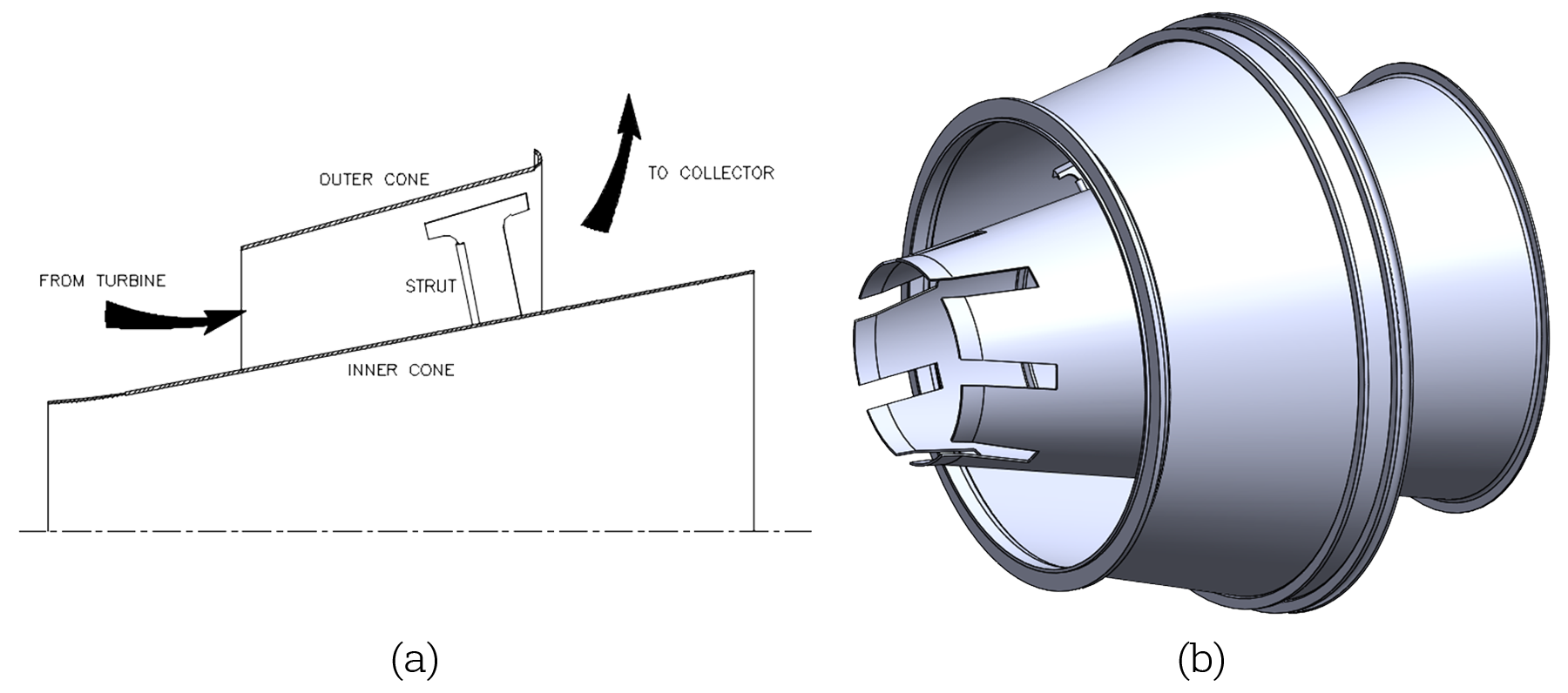
Figure 1: Exhaust diffuser (a) cross sectional view, schematic (b) 3D view
Naturally, the question arises: “Why has the structural design of exhaust diffusers remained a challenge despite the continued evolution of the aerodynamic design.” The answer to this question is multi-faceted. For one, the diffuser is often in the presence of a corrosive environment while being subjected to very high temperatures, making it more vulnerable to inter-granular attack due to sensitization. Another challenge is the handful of high frequency excitation mechanisms, such as strut vortex shedding and blade pass pressure pulsations, which can lead to numerous high-cycle fatigue failures. Unfortunately, the designer’s hands are often tied when it comes to the more straightforward approach: thickness-reinforcement of the parts. Exhaust diffusers are intentionally designed to be light, thin, and flexible structures which accommodate thermal growth and some level of rotational degree of freedom. This presents a challenge of competing goals: on one hand the diffuser must be light and “thermally flexible” while on the other hand the diffuser must also be strong enough to withstand various aerodynamic instabilities and excitations while operating in harsh environments. In this scenario, the RMS approach was multi-disciplinary: ranging from improving the materials of construction to carefully analyzing the stresses, the excitations, and the natural frequencies. This approach allowed a more reliable and targeted solution where the design could be selectively enhanced in key areas susceptible to failure without compromising on the aerodynamic aspects.
A customer operating a DR-22, 2-stage power turbine contacted RMS regarding a failed exhaust diffuser. The diffuser was in need of immediate repairs, but also a more long-term design solution that remedied the problem at its source and reduced the need for frequent repairs. Metallurgical analysis of the exhaust diffuser showed inter-granular cracking where the struts’ feet were welded to the inner and outer cones. Earlier experience with this machine indicated that the struts would fail consistently after several years of operation. Figure 2 shows the failure location.
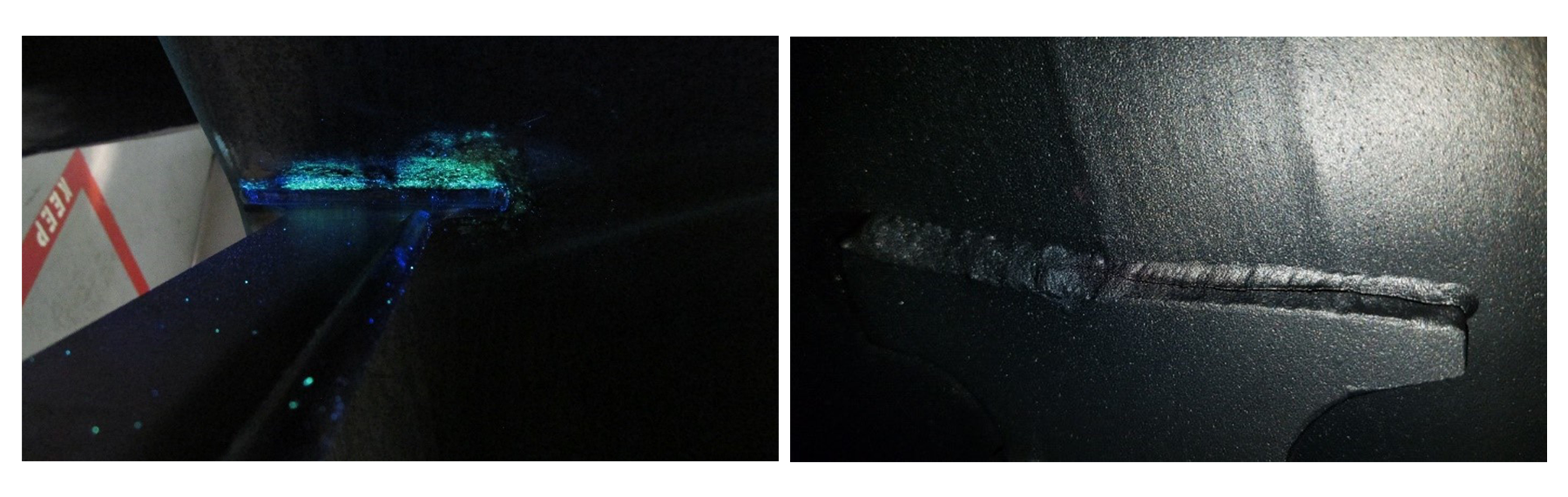
Figure 2: Extensive cracking at strut foot location and welding heat affected zone
Note that the diffuser was operating at temperature levels exceeding 1000 ⁰F in a corrosive environment. A reduction in the material endurance limit in this environment combined with the presence of aerodynamic excitations and lower frequency fundamental modes created the perfect storm for high cycle fatigue at the strut footing. Due to the multi-faceted nature of the problem, RMS adopted a multi-disciplinary approach involving material analysis and FEA modeling with the proposed a three-pronged solution:
- Improve the construction material
- Reduce the stress levels at the strut foot
- Decouple the excitations from the fundamental modes
Improve the Construction Material:
RMS improved the structural performance of the diffuser by upgrading from an older 316 SS material to a 321 SS material. The addition of Titanium in 321 SS opposes chromium carbide precipitation, enhancing the material’s resistance to sensitization in harsh environments.
Reduce the Stress Levels at the Strut Foot:
The RMS team created a finite element model of the diffuser to investigate the stress levels at critical locations and explore possible design solutions. The diffuser model presented some unique challenges. However, RMS’s extensive experience with the construction of power turbines facilitated an understanding of the loads and constraints for this particular application. One of the most common mistakes when creating finite element models is “over-constraining” the model. In this particular application, it was easy to fall into this trap as the bearing housing flange connection provided some restraint but allowed for rotation of the diffuser on a pilot ring to accommodate for thermal growth. Accurately representing this connection proved to be a critical task in constructing the finite element model, since the wrong model constraints lead to fictitiously overstressed components resulting in erroneous conclusions and therefore, bad design decisions.
The overall complexity of the diffuser model also presented a challenge. A variety of techniques such as periodic modeling and detailed sub-modeling of the welded areas allowed RMS to achieve good accuracy and fidelity at critical locations while managing the computational costs (See Figures 3 and 4).
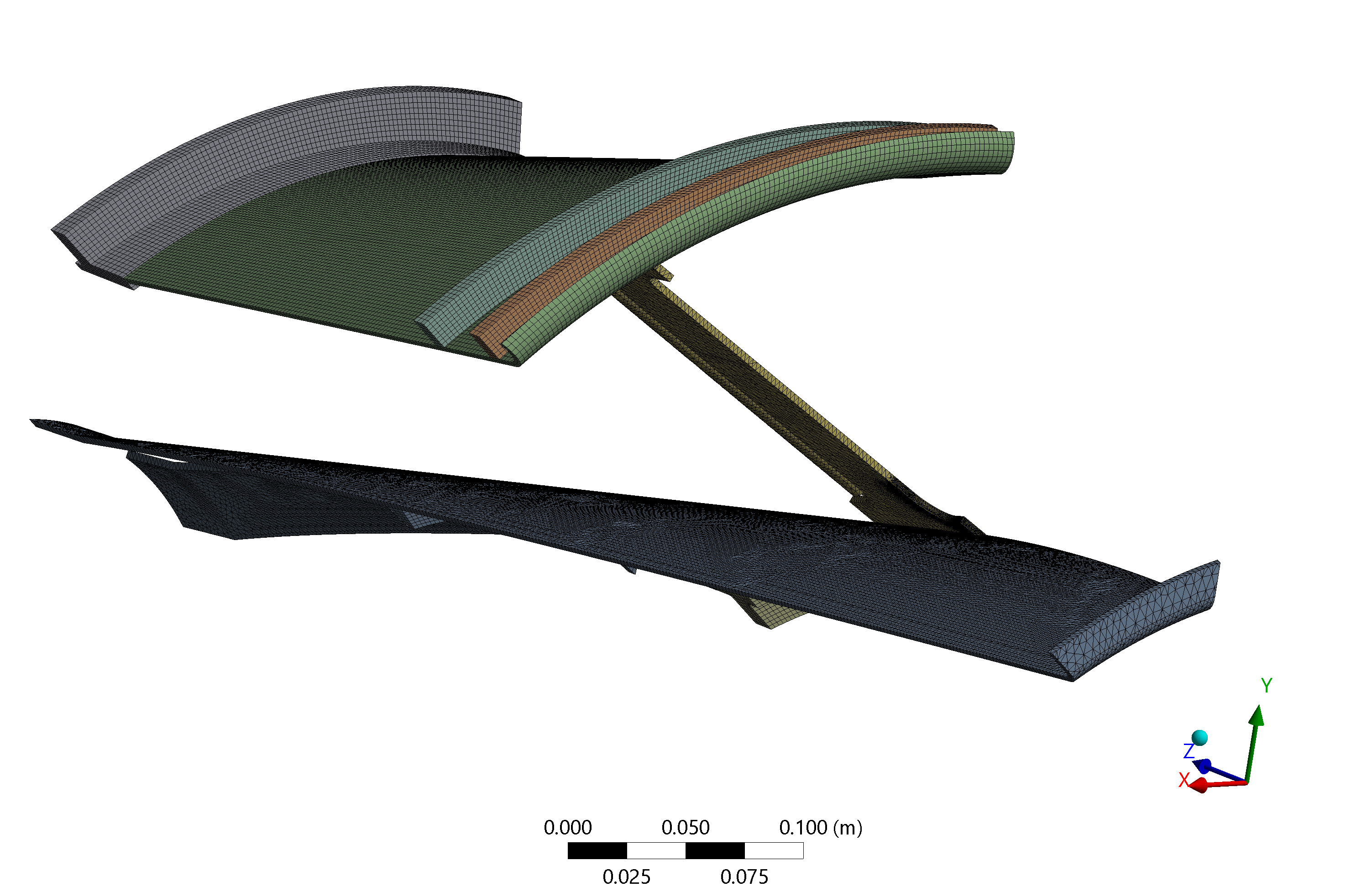
Figure 3: A periodic model of the exhaust differ enabled RMS to speed up solution delivery time
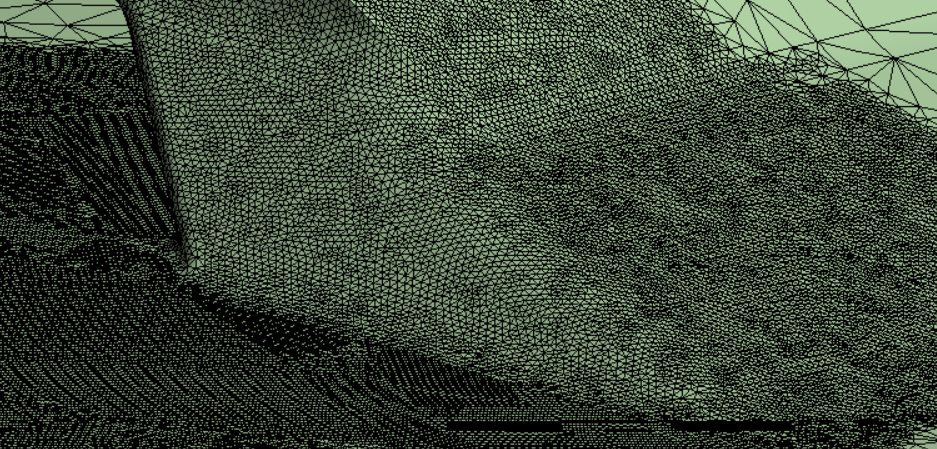
Figure 4: Localized sub-modeling allowed for intense accuracy and scrutiny of results in key failure areas
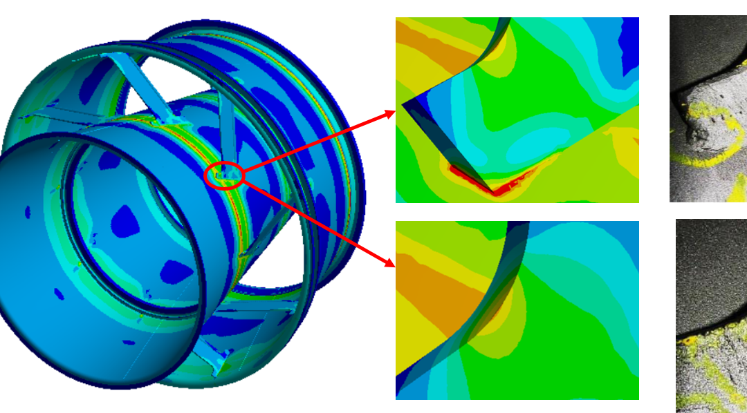
The presence of the bearing housing flange right underneath the struts along with the intense connection angle and the thermal growth of the struts relative to the cones caused high stress levels at the failure locations. The FE models created by RMS proved to be quite powerful in this case as the failure locations were effectively correlated to high-stress regions. Figure 5 shows this correlation.
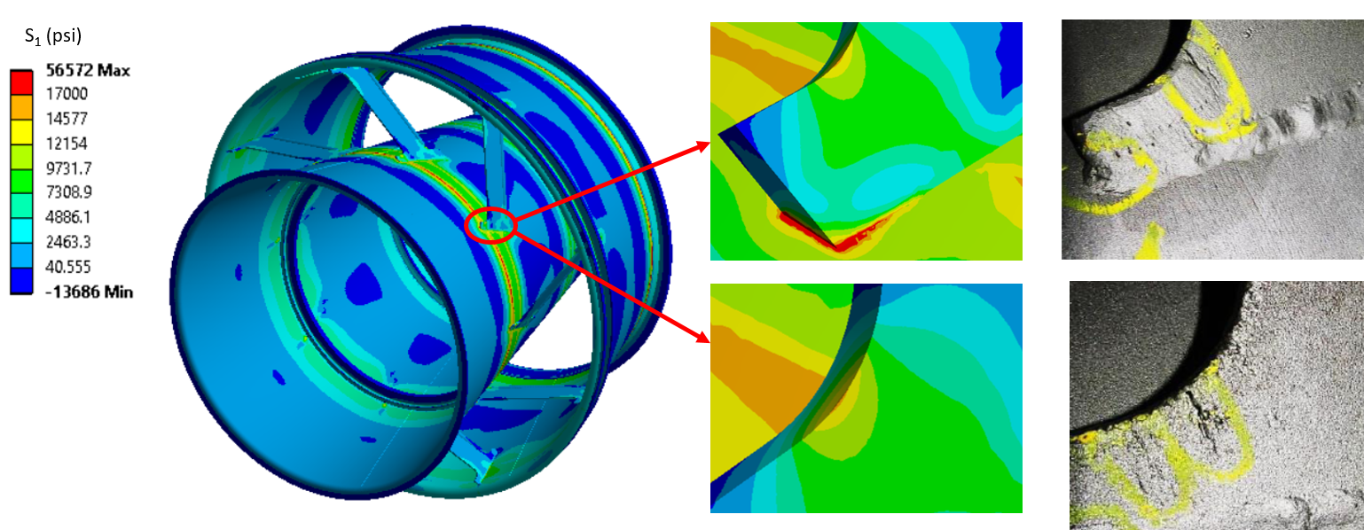
Figure 5: Correlation of failure location with structural analysis results
Using the correlated FE model at-hand, the RMS team evaluated several design alternatives for stress-reduction effectiveness, manufacturability, and reliability. The RMS design solution involved locally thickening the cones where the strut feet joined the cones (See Figure 6(a)). This solution proved to be more effective than local patch weldments since the gaps between the cones and the patches were eliminated while simultaneously reducing both the dynamic and static stresses due to the increased thickness (See Figure 6(b)). Also, the aerodynamic design and performance of the diffuser were preserved since none of the flow path features were disturbed or modified.
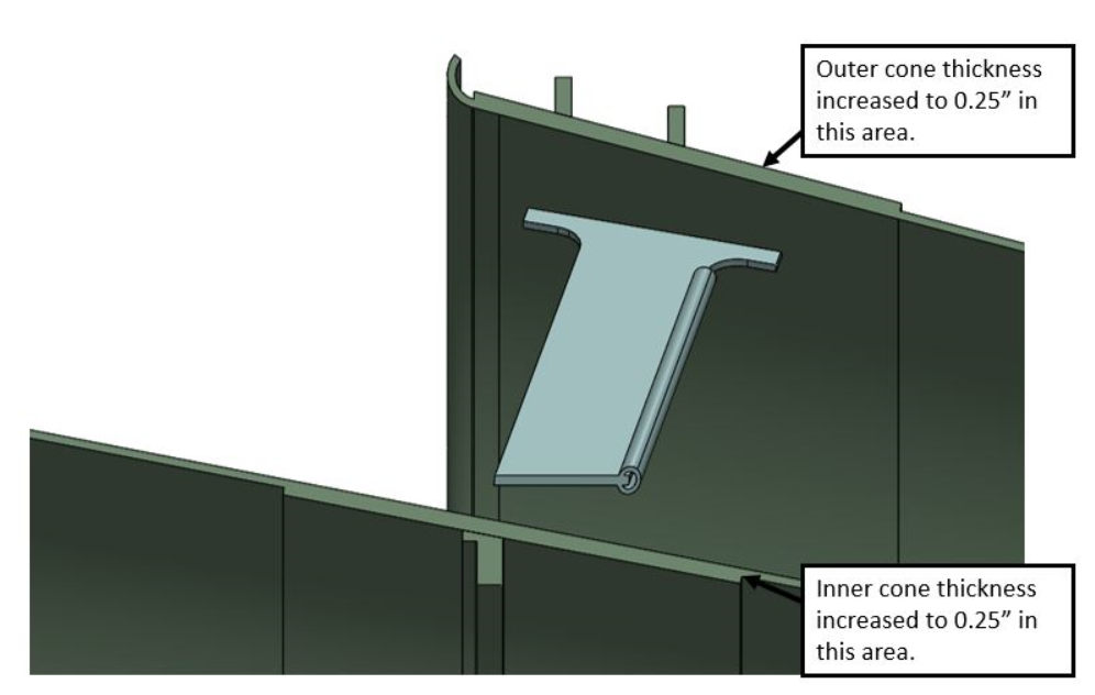
Figure 6(a): Improvement of diffuser structural design
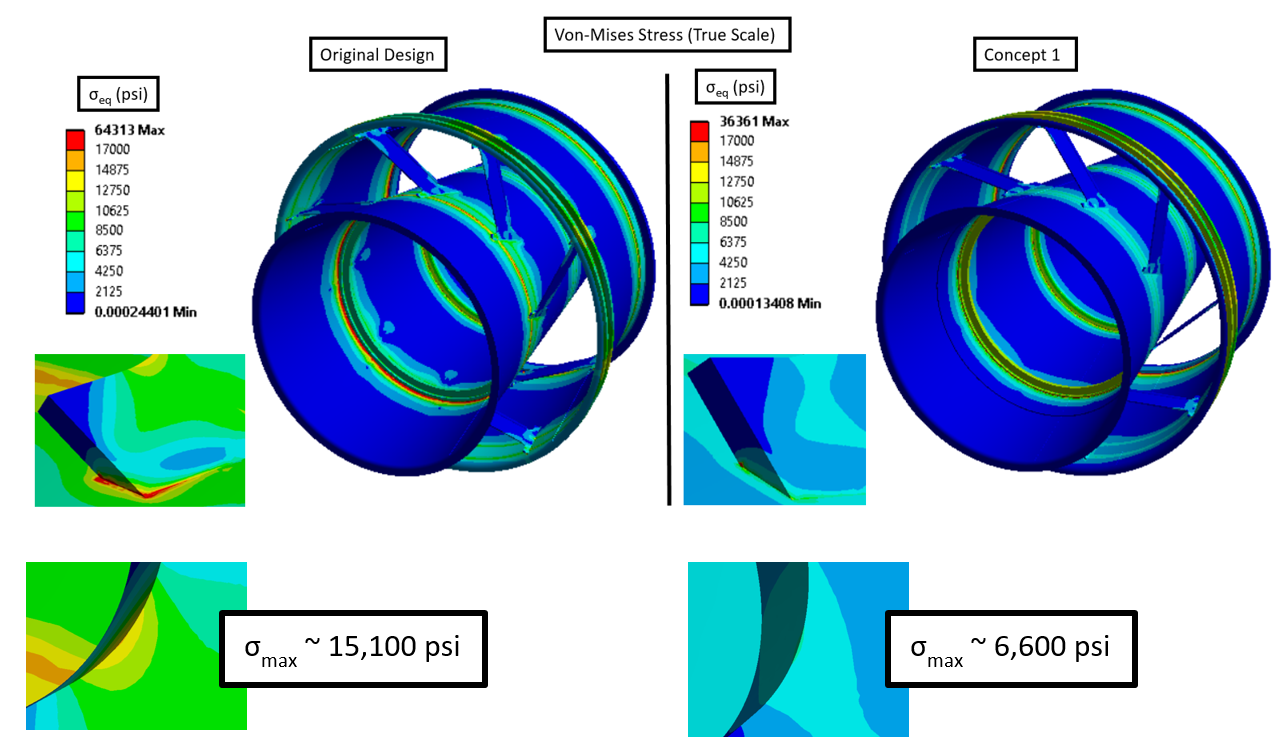
Figure 6(b): Proposed design mean stress levels before and after design enhancement
Decouple the excitations from the fundamental modes:
The analysis in the previous section dealt with the steady loads working on the diffuser. More often than not, rotating equipment is subjected to time varying dynamic loads on top of the static loads. In the case of exhaust diffusers, vortex shedding from the diffuser struts and rotor pressure pulsations work as cyclic excitation sources. The resulting dynamic loading is often not of concern unless it coincides with one of the fundamental modes of the diffuser. Fundamental modes are the simplest modes of vibration like simple panel modes or torsional strut modes. These fundamental modes are critical as they require only a small amount of energy to be excited. The fundamental modes are shown in Figure 7. In order to investigate the fundamental modes and their frequencies, RMS performed a modal analysis on the diffuser. Both the frequencies and mode shapes were vital outputs. When the shape and magnitude of excitation forces coincide with fundamental modes of vibration, high levels of alternating stress can result.
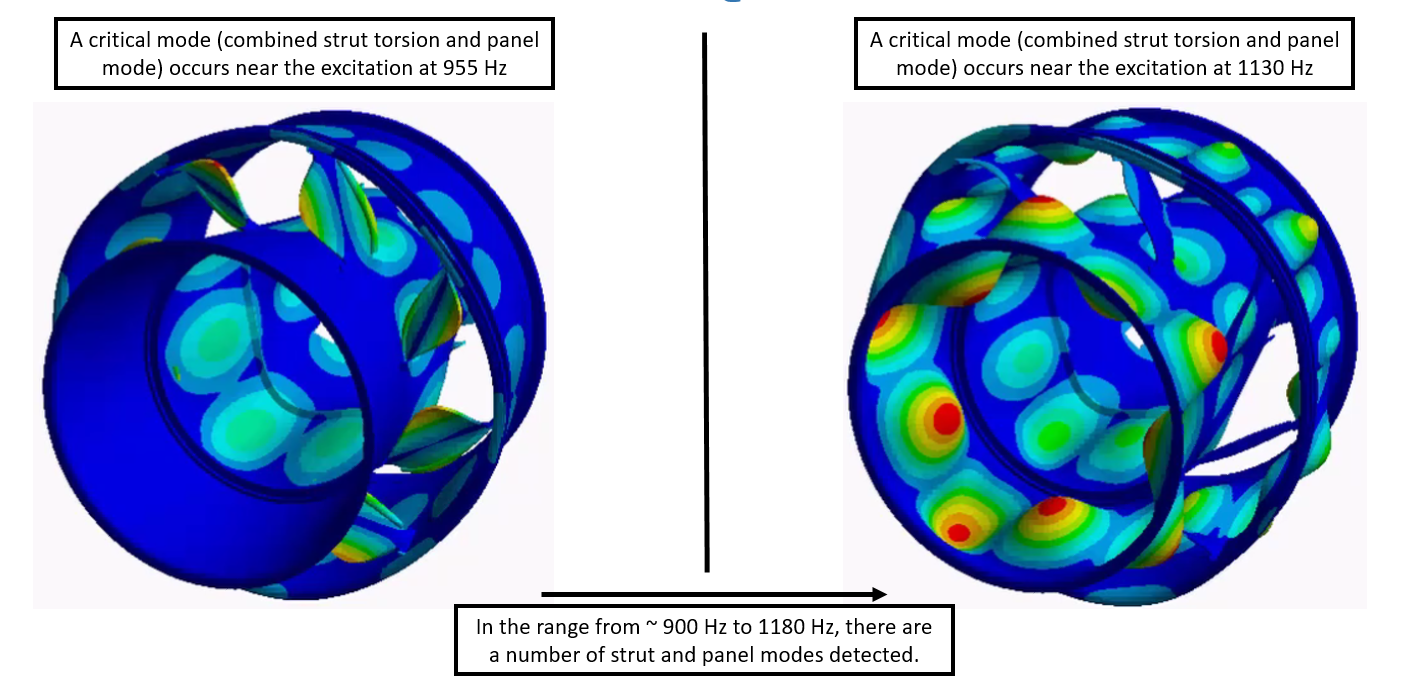
Figure 7: Fundamental torsional and panel modes with low separation margin to excitation frequencies
In most frequency analyses, the determination of excitation sources is relatively straightforward. Excitations are typically taken as machine operating speed and multiples of machine operating speed. If these excitation frequencies match up with or come close to fundamental modes, a resonance problem may result (resulting in high alternating stresses). For this analysis, RMS took a more rigorous approach. Not only were the excitation frequencies considered, but the shape of the excitations was also taken into account to account for the fact that the diffuser needed to be excited at the right frequency and in the right shape in order for high alternating stresses to result. To obtain the vortex shedding excitation frequencies, RMS used a combination of CFD modeling and hand calculations to obtain the corresponding Strouhal number for this specific geometry and application. The Pressure pulsation excitation amplitudes were estimated based on the dynamic pressure available through the annulus. Figure 8 shows the vortex bubble shed from the strut. There were shedding frequencies associated with the leading edge and the trailing edge for both the fore and aft struts.
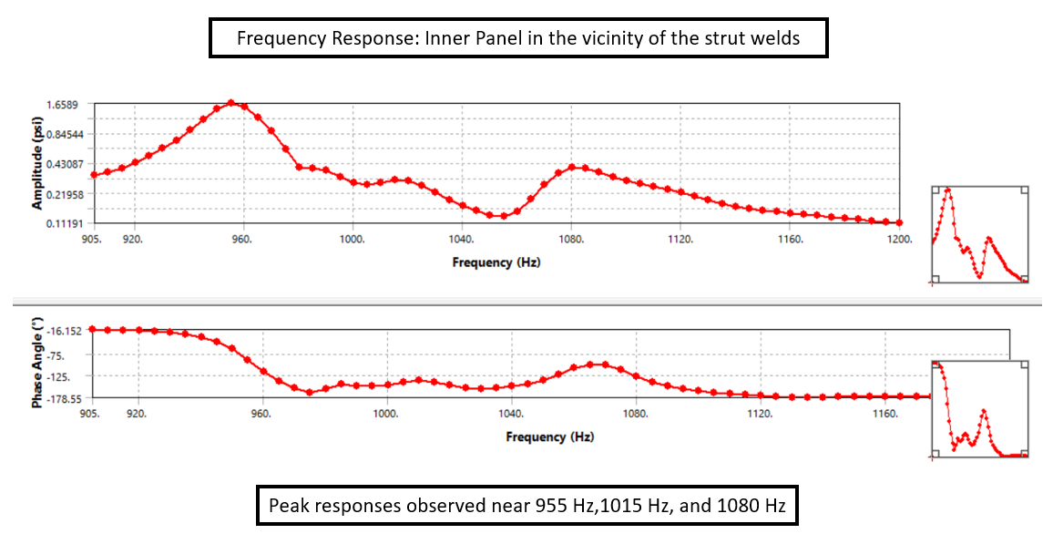
Figure 9: Resonance at fundamental diffuser modes, identified by harmonic analysis
After determining the vortex shedding frequencies and the pressure pulsation frequencies, a harmonic analysis was performed using the calculated excitations and mode shapes within the frequency range of interest. With the improvements in FEA and computational tools, this type of analysis effectively provided a more direct means of calculating the alternating stresses as opposed to the more wide-spread use of applying general amplification factors/safety factors to estimate alternating stresses. This type of analysis allowed the amplification factor to be directly calculated for this specific geometry and application. The resulting excitations showed a condition of resonance close to the fundamental modes, as shown in Figure 9. However, the proposed solution to thicken the cone sections close to the strut feet helped by increasing the local stiffness, thus shifting the fundamental modes to higher values and decoupling them from the excitation frequencies.
Finally, a complete understanding of the state of stress and the risk of High Cycle Fatigue (HCF) was obtained by plotting the static and dynamic stresses in a Goodman diagram for the original design and the improved design. Note in Figure 10 that the proposed solution reduced both the mean and alternating stress components, shifting the stress state to a much more reliable area inside the design envelope. The original mean stress level was sufficiently high such that only a small value in dynamic excitation/alternating stress could push the state of stress outside of the design envelope. In other words, there was a low safety margin available for diffuser vibration. Moderate stress levels and variations in those stress levels presented a significant HCF risk.
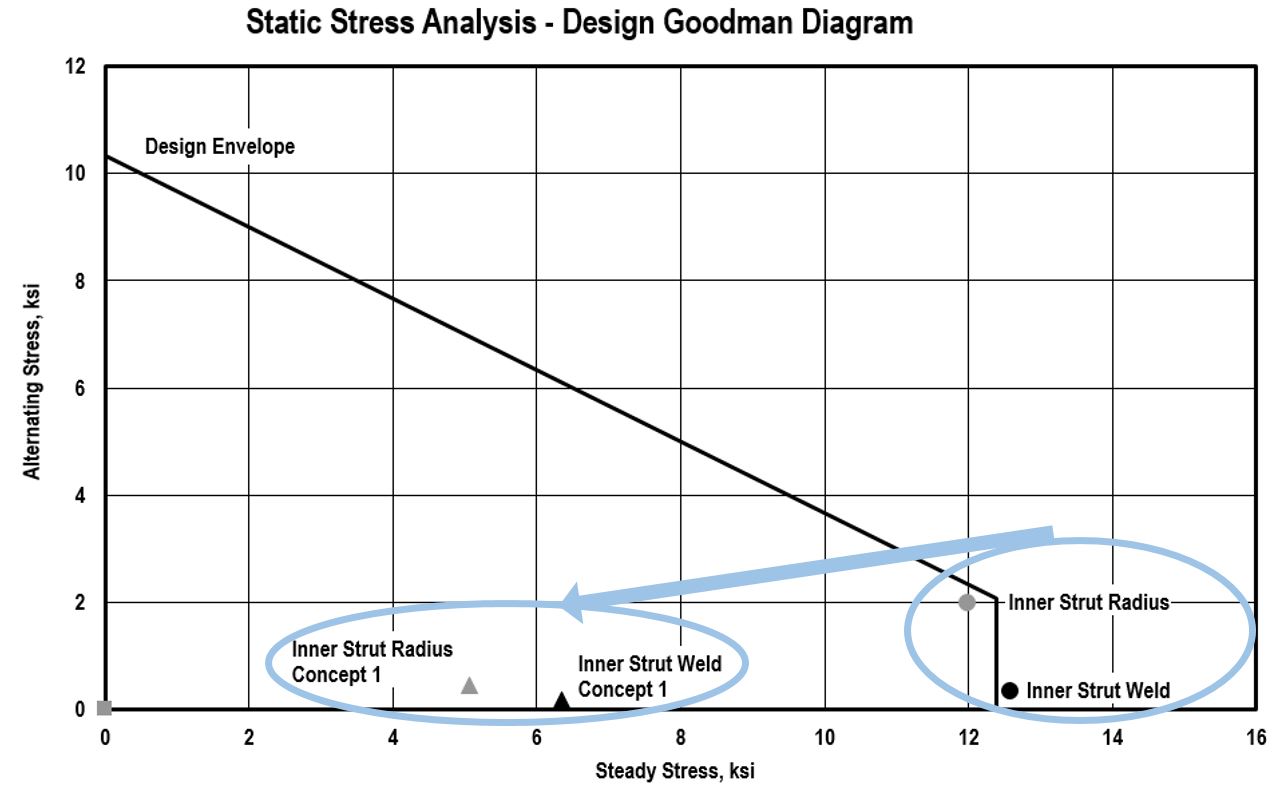
Figure 10: Goodman diagram shows marked improvement in structural health of the exhaust diffuser
Turbomachinery failures can be complex. Failure is very rarely caused by only one factor. In most cases, a combination or “perfect storm” of factors add up in some way to cause catastrophic failure of components. It is no surprise then that designing and innovating to avoid failure requires careful consideration of all the possible factors that can lead to failure. It is critical to have a multi-disciplinary, team approach that can specialize and identify all relevant issues in order to find a solution. This challenge was well suited to RMS’s multi-disciplinary team of specialists with extensive experience in turbomachinery repair, design, and analysis which lead to a long-term high-cycle fatigue solution for the customer.