
By Structural Analyst James Cardillo, CFPHS, EIT and Senior Aerodynamicist Ryan Montero
Fluid-Structure interaction (referred to herein as FSI) is a method that requires calculating a flow field using Computational Fluid Dynamics (CFD), and coupling fluid flow results to a solid structural analysis model (See Figure 1).
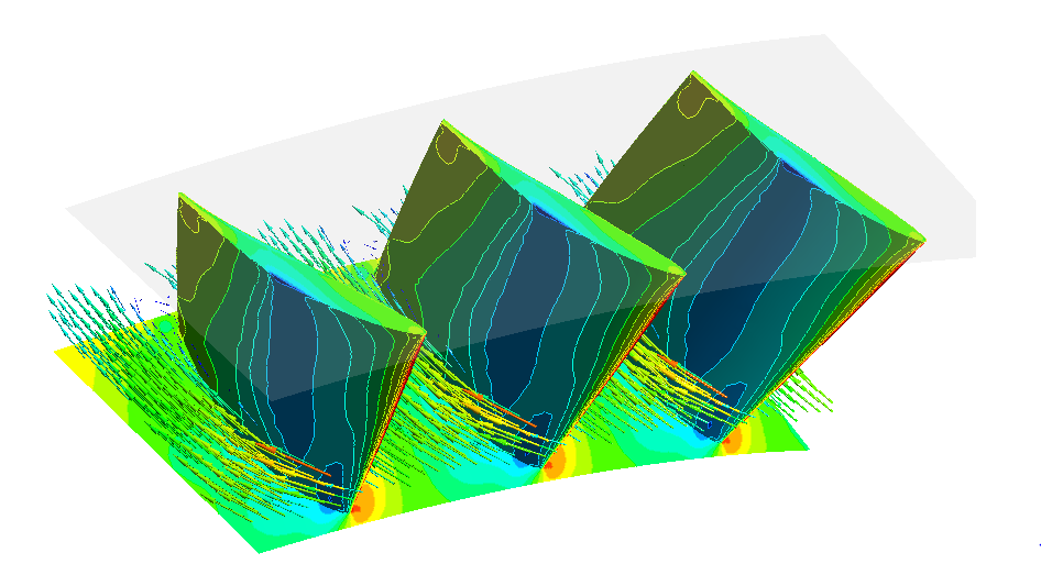
Figure 1: Snapshot of the Fluid-Structure Interaction calculation used in the current investigation. The flow velocity (gas flow) is shown by the colored glyphs. The flow field exerts a fluid force on the solid blades. The fluid force exerted on the blades is shown by the colored pressure contours on the surfaces of the blades.
This coupling allows the fluid and structural models to exchange information, creating a realistic simulation of how the fluid flow impinging on a solid body can cause deformations of the solid body (and in the reverse direction, how the deformations of a solid body can influence the surrounding fluid-flow).
Such a calculation requires considerable time, computational power, and effort. As a result, this type of calculation is often exclusive to academia, limited areas of industry, and engineering consultants. It has generally not been considered practical for broader industrial use. Typically, analysts calculate the flow field separate from the structural behavior of solid bodies. Simplifying assumptions and analytical approximations are often used to provide analysts with estimates of how a flow field might influence a structural body. However, with the continued development and availability of parallel computing, the need to solve fluid flows separate from solid body mechanics has diminished. The ability to couple these two calculations into one FSI simulation has become faster and more accessible. RMS strives to stay current with the most advanced analysis techniques, so it comes with no surprise that RMS has adopted this technology in its latest failure investigation: a situation involving the operation of an axial compressor in “choke” which lead to the eventual catastrophic failure of the compressor disc and blades.
The use of FSI in the latest failure investigation has allowed RMS engineers to gain insights into some of the more complex physics of turbomachinery, including the intricate flow patterns and structural vibrations that operating an axial compressor in choke can produce. Figure 2 below shows a choked flow-field snapshot of the pressure in stages 1 and 2 (top-down section view) of the axial compressor under investigation. Choke operation of the axial compressor created pressure pulsations in the flow field that impinged on the axial compressor blades. These pulsations repeatedly loaded and unloaded the blades, leading to structural vibrations.
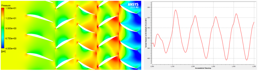
Figure 2: Snapshot of a flow field (left) showing light pressure pulsations encountered in choke operation. The pulsations were subtle, but enough to create a fluctuating “moment” or torque on the blade which is shown by the line plot of blade moment vs. time (right).
As the pressure magnitude fluctuated, so did the pressure distribution on the blade surfaces. As shown in Figure 3 (below), the pressure distribution on the blades was highly non-uniform, creating unbalanced forces on the blades that would be nearly impossible to model accurately without FSI. The pressure distribution shown in Figure 3 was calculated from the flow field and directly applied to the blade structural (periodic) model using FSI.
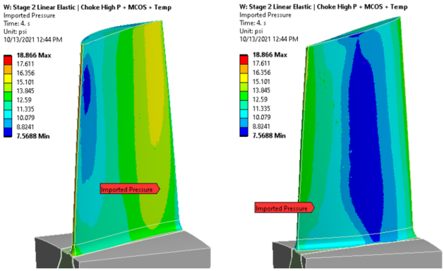
Figure 3: Contours showing the pressure distribution created by the flow field on the pressure and suction surfaces of the blade. The color contour shows how highly non-uniform the pressure distribution is.
This transfer of fluid pressure to the solid body was done in real time as the flow and pressure distributions evolved. The end result was a hyper-realistic simulation of how the blades vibrated in the presence of the oscillating flow field. The ability to avoid making approximations and simply allowing the flow field to directly impact the blade structural model was paramount to understanding the situation at-hand which involved low-amplitude oscillations created by a fluctuating fluid pressure field. The low-intensity vibrations encountered did not lead to high-cycle fatigue failure of these blades in the conventional sense. Stress-life calculations demonstrated that the low amplitude vibrations produced low alternating stresses in the blades and in the disc dovetail slots as shown by the Goodman diagram in Figure 4 below. The critical points at the airfoil base fillets and the disc dovetail groove were well within the design envelope for infinite life.
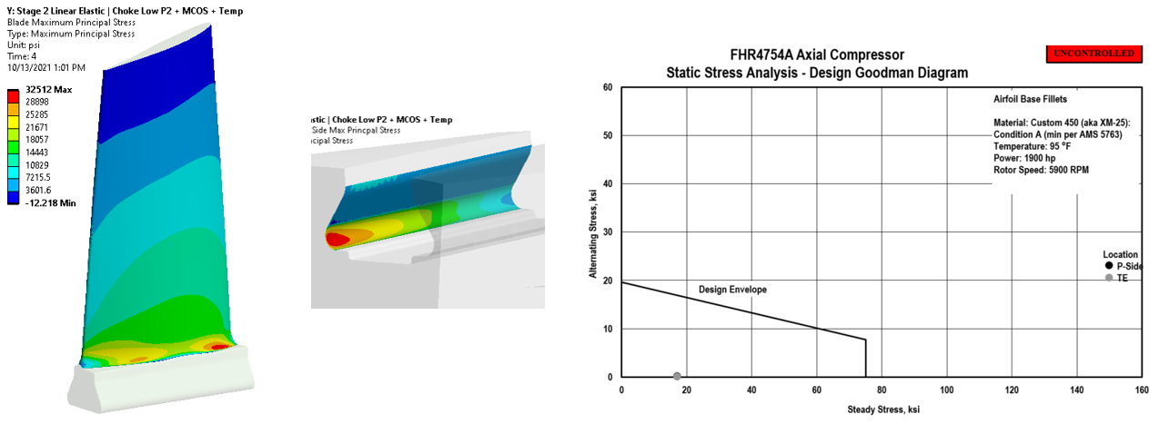
Figure 4: The FSI loads created deformations and tensile stresses in the structural model with critical points at the base fillets (left) and the disc dovetail groove (middle). Still, the magnitude of these alternating stresses was low and within well-established design limits as shown by the Goodman diagram (right).
This result was initially perplexing. However, it was accurate: alongside an ongoing metallurgical investigation of the failed compressor, it became clear that the physics predicted by the FSI model were indeed accurate. High cycle-fatigue alone did not explain this machine failure. In this situation, another type of failure was the initial culprit: fretting.
Fretting is a type of failure that often occurs when two metal bodies under high compressive stresses experience small, relative oscillatory motions. During fretting, high points or asperities of the impinging surfaces momentarily bond and detach from one another, dislodging small particles and leaving small, shallow pits along with powdery debris. The pits left behind by fretting can create very high stress concentrations. In the presence of these stress concentrations, benign tensile stresses can become problematic, leading to crack propagation and eventual failure. The powdery debris left behind oxidizes and forms a red, rust-like powder on the impinging surfaces. When investigating a failed part, this red powder is a tell-tale sign that fretting occurred. The FSI model used was not capable of directly simulating the creation of pits and debris due to fretting. However, it was able to show that the conditions for fretting to occur did exist, mainly: 1) high compressive stresses creating an impingement point between two metal surfaces and 2) small oscillatory motions at the impingement point. Figure 5 below (top left) shows the compressive contact stresses in the disc dovetail groove at the end of the contact point between the blade and the disc, providing clear evidence that high, compressive contact stresses were present.
In addition to this, the same FSI model was used to calculate the relative displacements between the two contacting bodies by measuring the displacements at the high point of the choke cycle and the low point of the choke cycle (refer to again Figure 2 above which shows the cyclic nature of the aerodynamic loading on the blades during choke). Figure 5 (bottom) below shows that small, oscillatory motions between the two contacting bodies at the point of impingement were indeed present. Clearly, the conditions necessary for fretting were present. The final piece of evidence presented itself by investigating the actual failed part. A photograph of the failed part is shown in Figure 5 (top right side). This photograph tells the final story. One can observe clearly the crack line almost exactly coincident with the impingement line predicted by the FSI model. Also, the tell-tale sign of fretting was evident: a red, powdery, rust-like debris left behind near the failure surface.
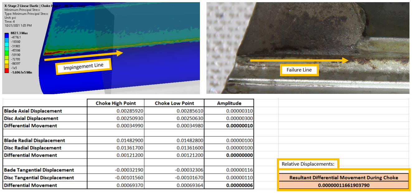
Figure 5: High compressive stress predicted from the FSI model (left) along with the actual failed part in the same location (right) with rust-like debris providing further evidence for fretting. Small oscillatory displacements (bottom) demonstrated that all conditions necessary for fretting to occur existed during choke operation.
At this point, the main offender in the failure investigation had been unmasked. The small, oscillatory motions of the blade in the disc groove during choke operation coupled with the extremely high compressive stresses lead to the creation of a fretting failure sites. From there these failure sites, cracks propagated during continued operation of the compressor until finally, the disc cracked all the way through its thickness. Further metallurgical evaluation confirmed all of these findings.
The solution would involve a combination of design changes to make the compressor blades more robust during choked flow and increased flow capacity operation. Additional treatments would also be added to the disc groove surfaces to provide protection against fretting and subsequent fatigue failure. These findings and the subsequent solutions for the customer were made possible by the use of FSI. The FSI model allowed RMS engineers to model the complex, transient aerodynamic loads on the blade which established the small, relative displacements of the blade in the disc groove. Without this tool, the complex situation and failure that ensued would have been difficult to model. As RMS continues to make use of advanced fluid and structural modeling tools, there is no doubt that valuable insights into previously overlooked phenomena will be gained, paving the way for new, innovative design solutions.