
The analysis and “fine-tuning” of centrifugal compressor impellers is often an iterative process. It involves balancing the aerodynamic performance requirements with the structural integrity and vibration characteristics of the impeller. The process is involved, but when executed properly, it can result in a high-performance, robust impeller design that runs smoothly and reliably.
Typically, the initial design of a centrifugal compressor impeller takes place upstream of the structural analysis. Once the initial design which satisfies the application requirements is obtained, a structural analysis is carried out on the impeller design to finalize its form and ensure its structural integrity. There are three core “pillars” or “tasks” when carrying out structural analysis of centrifugal compressor impellers:
- Fit Analysis of the Impeller: A comprehensive analysis of the “worst-case” fit stresses and power transfer characteristics of the impeller to shaft assembly.
- Stress Analysis of the Impeller: A detailed analysis of the stresses and deformations in the impeller design itself (local Von-Mises stresses, Maximum Principal Stresses, deformations, etc… in the blades, the cover plate if applicable, and the disc of the impeller). In some cases, the severity of the application may lead to deeper investigations (such as plastic deformations, thermal transient behavior, low-cycle and high-cycle fatigue, etc…)
- Vibration Analysis of the Impeller: The frequency characteristics of the impeller design are analyzed to ensure good separation between natural frequencies and known excitations. In some cases, where unique loadings and excitations are present, a harmonic analysis is carried out to further characterize the vibration response and fatigue behavior of the impeller design.
In almost all cases, these three pillars aren’t completely independent of one another. Thus, changes or findings based on one pillar of analysis often affects results from another pillar. The results and outcomes of these pillars are frequently linked to the initial design and application requirements as well as the aerodynamics for the centrifugal compressor. For these reasons, the analysis and design process is often very iterative and multi-disciplinary. Finite Element Analysis (FEA) is a key tool used in the structural analysis process. This tool is used in combination with performance testing and industry experience to drive an impeller design to its final form.
Pillar 1: Fit Analysis of the Impeller
One could say that the performance of a centrifugal compressor impeller is limited by the power transfer from the shaft to the impeller itself. This makes the fit characteristics of the impeller extremely important. An impeller with an improper shaft fit can also adversely affect the vibration characteristics of the machine. In the fit analysis of a centrifugal compressor impeller, the main area of interest is the fit of the impeller onto the driving shaft, which is almost always an interference fit. In some cases, a “key” is added to this fit to ensure redundancy and safety in power transfer. However, in the design and analysis phase, all fits are treated as “keyless” interference fits. This forces a reliable and conservative design that satisfies requirements safely without relying on design redundancies or “back-ups” to perform reliably. Interference fits pose several design challenges:
- The interference needs to be strong enough such that the shaft transfers enough power to the impeller without “slipping” or sliding.
- The interference shouldn’t be so severe that it creates extremely high “hoop” stress in the impeller bore.
- The fit must meet these requirements in the course of design operating speeds and thermal gradients.
- The fit must be practical in the sense that the impeller can be mounted and dismounted from the shaft without damage.
Two-dimensional, axisymmetric finite element analysis models like the one shown in Figure 1 are heavily used to ensure that an interference fit satisfies the above requirements. The advantage of this type of model is very high computational efficiency such that many design iterations can be performed quickly to arrive at the optimal fit requirements. The final fit used for an impeller design is guided by the outcome of the finite element analyses in combination with field testing and experience. In certain applications where the geometry does not permit the use of an axisymmetric model, a full three-dimensional model or a periodic model may also be used.
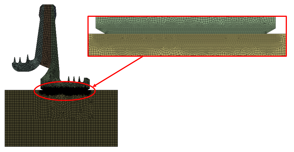
Figure 1: 2-D, typical axisymmetric finite element model mesh used in an impeller fit analysis. Particular emphasis is placed on the area of the impeller bore since the physics in this area are key to the analysis of the fit.
Centrifugal compressor impellers are flexible bodies that deform when under load (at rotational speed). Because of their shape, they have a tendency to “lift” away from the shaft at the aft-end of or the back of the bore as shown in Figure 2.
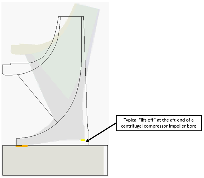
Figure 2: 2-D, deformed shape showing the lift-off experience at the aft-end of a centrifugal impeller bore when rotational speed is applied.
Typically centrifugal impeller bores deform in this way at speed (even if the interference fit is along the full bore of the impeller). This presents a design challenge because at speed, power transfer is really only taking place over the portion of the fit which remains in contact (the inlet side of the impeller bore). The design of a fit like this requires that the engineer size the length of the fit and the amount of interference to ensure that it remains in contact and transfers power when the impeller is run at speed. This requirement can be further complicated when high, differential temperatures are applied to the impeller and the shaft (which could cause the impeller to expand away from the shaft and lose contact). The process is very iterative with the 2-D finite element analysis being a key tool used to arrive at the design of the bore interference geometry. Typically, a range of fits and temperatures are modeled as well as various bore geometries. The remaining contact length and power transfer capabilities are calculated over a range of fits from the finite element model as shown in Figures 3 and 4. These calculations provide the engineer with the design insights needed to size and design the optimal fit. For the particular impeller shown in Figure 3, it can be observed that after the interference fit reaches a certain level, the entire front of the bore remains in contact at speed. Thus, making the fit more aggressive provided no additional benefit at speed.
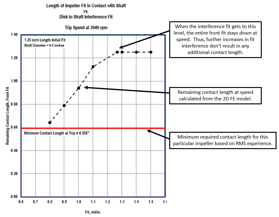
Figure 3: 2-D, deformed shape showing the lift-off experienced at the aft-end of a centrifugal impeller bore when rotational speed is applied.
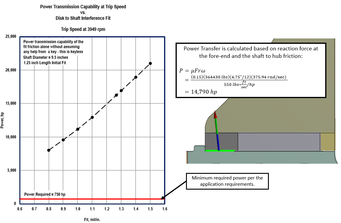
Figure 4: Results of 2-D, Power transfer analysis shown over a range of interference fits.
Adequate power transfer and remaining front contact length are critical for the design of the interference fit, as well as the resulting hoop stresses in the bore of the impeller. When an impeller is interference fit onto a shaft, this causes expansion of the bore of the impeller, resulting in “hoop” stress. If the hoop stress is too high, it can lead to deleterious plastic deformation of the impeller bore. Therefore, hoop stresses during assembly (shown in Figure 5) as well as during operating conditions are calculated from the structural analysis. The engineer must ensure that these stresses remain below the yield strength of the material at the selected fit with adequate safety margin to guarantee performance and reliability of the fit.
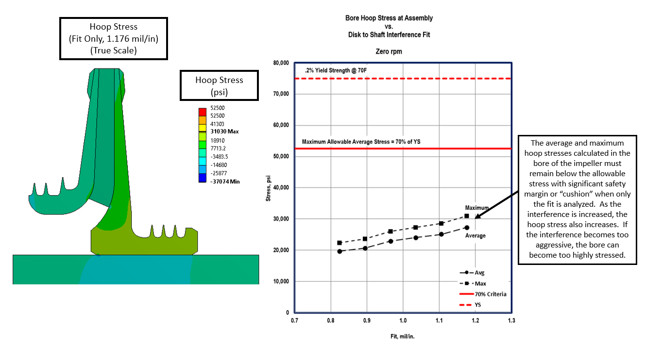
Figure 5: Hoop stresses calculated in the bore of the impeller over a range of interference fits used to aid the engineer in selection of the proper interference fit.
Pillar 2: Stress Analysis of the Impeller
Centrifugal compressor impellers are often exposed to harsh operating environments. These environments include high centrifugal forces from the rotational speed of the impeller, aerodynamic forces on the blades, high temperatures and thermal gradients, as well as the possible presence of corrosive gases. These factors can combine to create high forces and thus high deformations of the impeller body. Therefore, in addition to satisfying the application pressure requirements, a centrifugal compressor impeller must also be strong enough to withstand high operating forces and loads without experiencing large plastic deformations or cracking. The materials for the impeller must be selected to maintain adequate design safety factor against the material yield strength and ensure compatibility with the working fluid. The impeller itself must be adequately smooth and contoured to avoid excessive stress concentrations which could escalate to fatigue cracks. If welds are present, these also need to be sized and performed properly to avoid excessive stress concentrations which would result in weld cracking. Once again, finite element analysis in combination with experience and testing is a key part of this process. In the case of analyzing the impeller design, full, three-dimensional finite element analysis is almost always necessary.
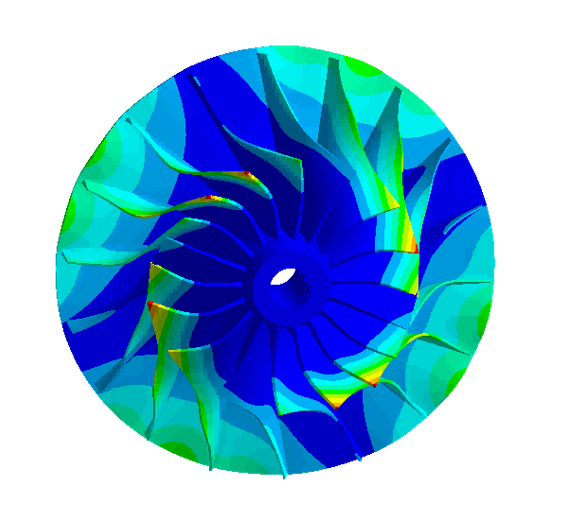
An overall sense of the impeller design and insight into critical areas can be obtained by calculating the Von-Mises stresses in the impeller when subjected to the operating loads as shown in Figure 6. The Von-Mises stress is basically a calculation of all of the distortion energy in the structure at a particular location. This calculation gives design engineers an indication of where the high risk areas are located in an impeller design. Typically, as a general design criteria, it is desirable to keep the Von-Mises stresses below the yield strength of material (with adequate safety factor) wherever possible.
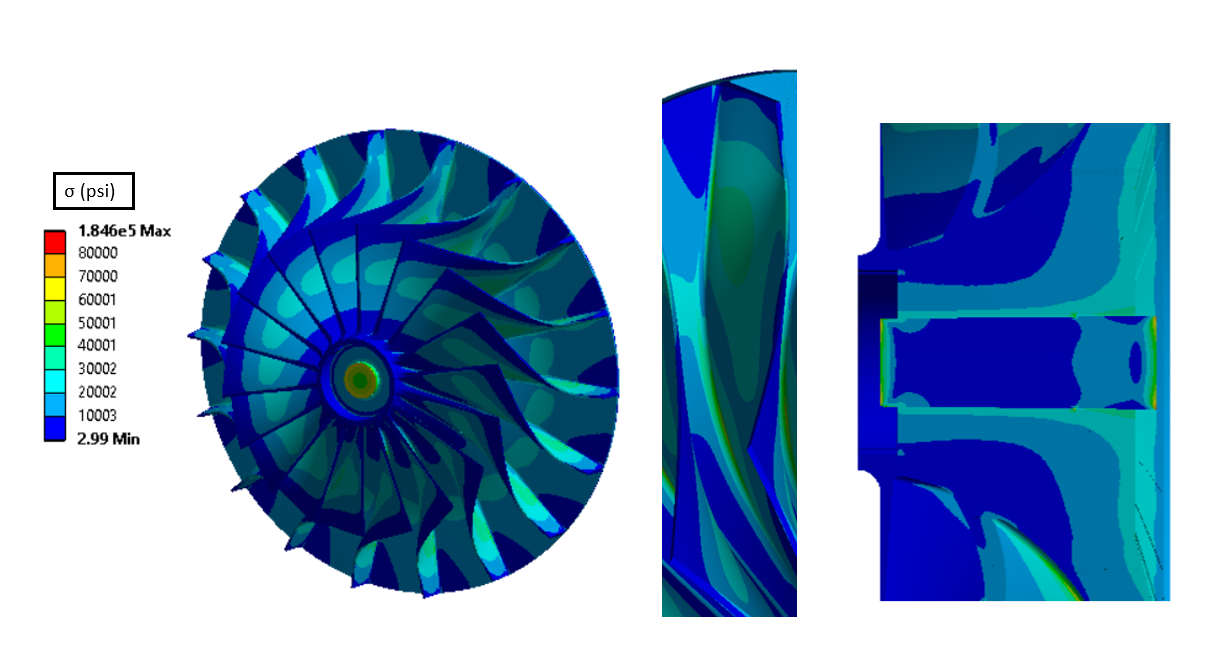
Figure 6: Von-Mises stresses calculated throughout the impeller show critical areas in the blade radii and the bore.
While Von-Mises stress provides insight into the critical areas of an impeller design, it doesn’t tell the whole story. Von-Mises stresses don’t provide information about the direction of a stress (IE: is it tensile or compressive?). Depending on the direction of the stress, the potential failure modes and design criteria may be different. Thus the corrective action a design engineer must take to safeguard against a particular type of failure varies depending on the direction of the stress. For this reason, Maximum and Minimum Principal stresses are also evaluated throughout the impeller as shown in Figure 7. Maximum Principal stress gives the engineer a sense of where the highest tensions occurs in the structure (highest potential for tensile crack growth and propagation). In contrast, the Minimum Principal stress provides the engineer with information about where the highest compression occurs. Other types of stress classification (hoop stress, circumferential stress, bending stress, etc…) are also utilized depending on the needs of the design engineer.
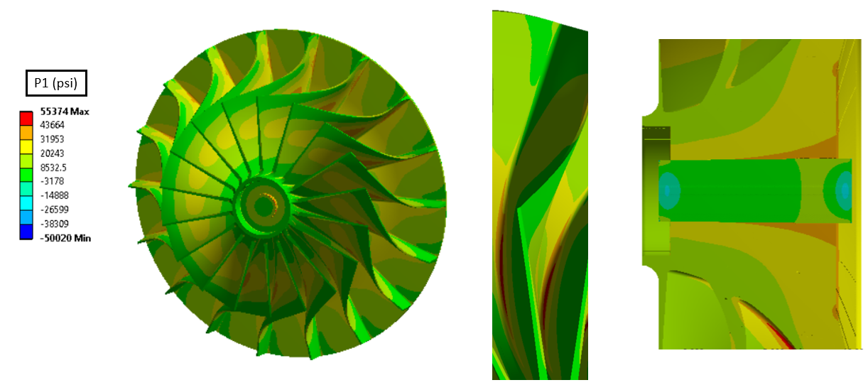
Figure 7: Maximum Principal stresses calculated throughout the impeller show areas of highest tension in the radii.
Thermal stresses add another degree of complexity to the impeller design. While uniform temperatures result in relatively straight-forward thermal expansions that need to be evaluated, a more deceptive challenge is the presence of high thermal gradients throughout the impeller body and the shaft. High gradients and transient temperature differences can result in differential thermal expansion within the impeller body itself (resulting in high internal stresses) as well as expansion of the impeller away from the shaft (resulting in the loss of fit mentioned in the 1st analysis pillar). Calculation of these thermal stresses can aid the design engineer in proper selection of materials and shaping the impeller to withstand high transient thermal stresses.
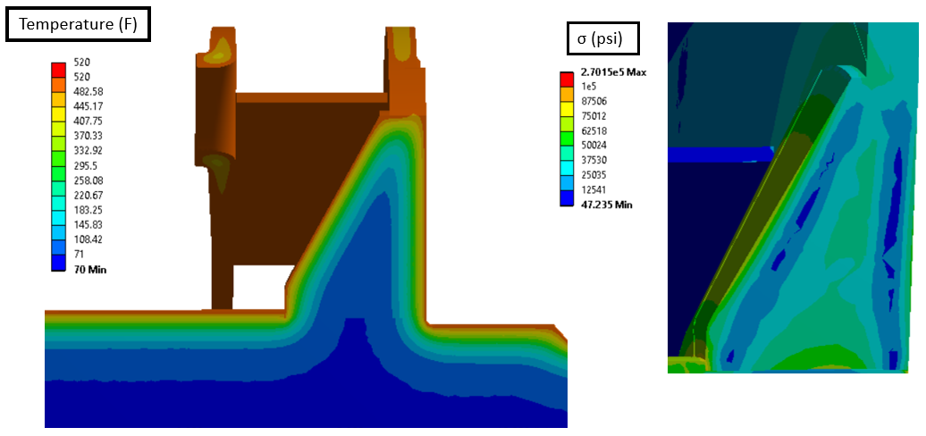
Figure 7: Thermal transient temperature distribution (left) shows non-uniform heating of the impeller hub in the bore area. The resulting stresses (right) show differential thermal expansion of the shell away from the core creates internal stress in the hub.
Finally, if high local stresses and plastic deformations are unavoidable, elastic-plastic analyses may be carried out to determine the degree of plasticity experienced by the impeller and the low-cycle fatigue life.
Based on all of the stress analyses, if the design is not adequate, changes to the geometry and/or materials need to be made. These changes sometimes result in a change in the aerodynamic performance and the fit performance of the impeller. Thus, the process is very iterative: when one aspect of the design is changed, the other aspects often need to be re-evaluated to determine their performance. This iterative process often repeats until an optimal, balanced design is obtained.
Pillar 3: Vibration Analysis of the Impeller
Centrifugal compressor impellers in rotating machines are subject to frequency excitations. The design engineer must ensure that these frequencies don’t excite the natural frequencies of the impeller. Excitation of the impeller’s natural frequencies can lead to catastrophic deformations and stresses as well as fatigue damage to the impeller. In the design phase, structural finite element analysis is used to calculate the natural frequencies of the impeller and to ensure that these frequencies are adequately far away from the excitation sources to avoid resonance. In rotating machines, the primary excitation forces are caused by aerodynamic wakes from stationary components like stators and struts (Figure 8). However, rotor imbalance, casing ovalization, and compressor surge/stall may also create excitation forces. While measures are sometimes taken to mitigate these excitations, it is more common for the design engineer to modify the impeller geometry in order to move the natural frequencies away from these excitations. This modification is typically an iterative process in which the design engineer modifies the impeller geometry or material, and the structural analysis is run to show how the natural frequencies were shifted as a result of the changes. The process is continued until the design engineer has obtained adequate separation margin (the natural frequencies are sufficiently far away from all known excitation sources).
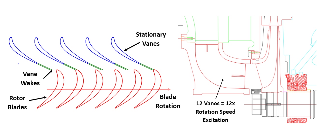
Figure 8: Illustration of compressor excitation sources.
Impellers are geometrically complex structures. As a result, their natural frequencies can also be quite complex. For an open-faced impeller, the natural frequencies are usually identified as a combination of blade modes (Figure 9 left) and “disc” modes (Figure 9 right). However, because the blades and the disc of an impeller are combined into one structure, there is also an interaction between these otherwise separate modes. Therefore, there is usually a large number of natural frequencies and combinations of blade and disc modes that need to be identified using structural analysis.
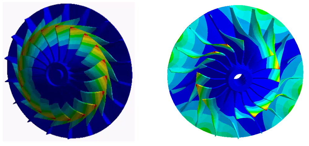
Figure 9: Impeller natural frequencies: 1st Blade bending frequency (left) and two-nodal diameter disc frequency with some blade interaction (right).
In the case of a closed-face impeller, distinct blade modes are harder to identify as the cover piece tends to bond the blades together creating a situation where the disc modes are more readily identified.
Depending on what types of modes or frequencies are identified by the structural analysis and which frequencies need to be changed, the design engineer may make geometric changes to change these frequencies. For example, if the structural analysis identifies a blade mode close to an excitation, the design engineer might alter the blade thickness or taper to move this blade mode away from the excitation. On the other hand, if the structural analysis identifies a disc mode near an excitation source, the design engineer might change the disc thickness to move the frequency. As stated before, these types of changes might result in a change to the performance and state of stresses in the impeller. Therefore, this pillar is closely coupled to the other pillars and aspects of the design. The process requires iteration and re-evaluation of the design until a proper balance is found. Typically, a Campbell or SAFE diagram is used to show the design engineer where the impeller natural frequencies lie with respect to the excitations. If an excitation crosses a natural frequency close to the operating speed on a Campbell Diagram (Figure 11), this is an indication that this frequency might be excited. Thus measures need to be taken to shift the natural frequency by altering the design or changing the material of the impeller.
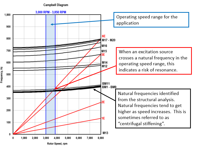
Figure 11: Campbell diagram for an open-faced impeller.
Finally, the fabricated impeller is often frequency tested (Figure 12) to validate that the frequencies identified in the structural analysis correlate well to the real natural frequencies, and as a final check to ensure that there is adequate separation margin from the excitation sources.
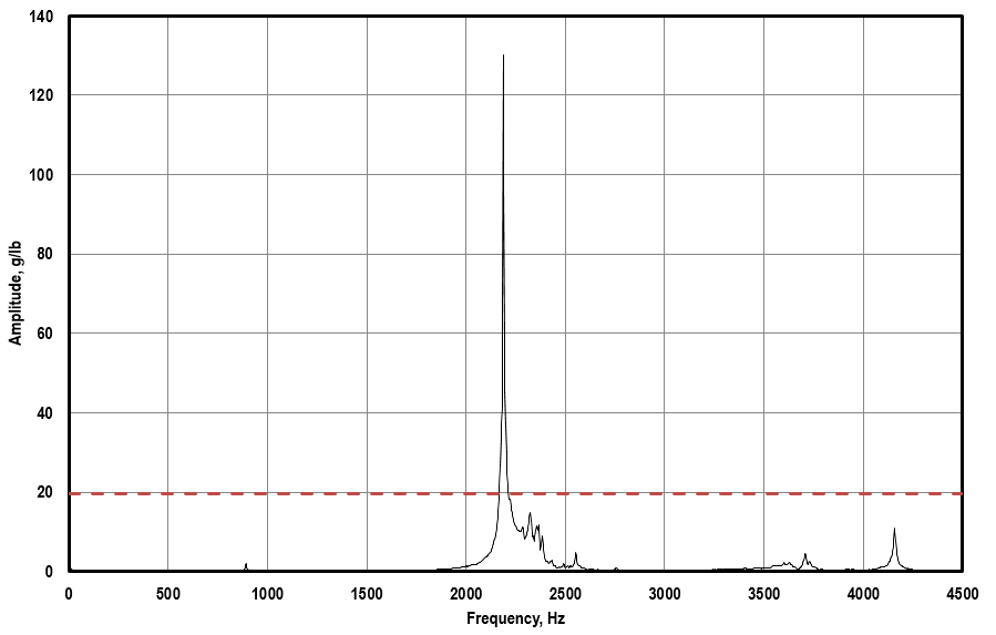
Figure 12: Typical frequency response from a frequency test shows peaks occurring at natural frequencies.
In conclusion, the structural analysis and final design of centrifugal compressor impellers is a complex process with inter-woven parts. The process can be separated into three main tasks or pillars, but these pillars are closely coupled to one another. Changes made as a result of the structural analysis can result in significant changes to the performance, cost, and complexity of the impeller. Therefore, the process is very iterative and multi-disciplinary process. RMS has a deep history with centrifugal compressors with the expertise and experience to design impellers that perform reliably and exceed expectations.